线结构光视觉传感器/线激光深度传感器标定工具(续)
线结构光视觉系统有着结构简单、使用灵活、受周围光照环境影响小等一系列特点,在实际中得到广泛的应用。在该技术的使用中,标定是避免不了的一个环节。线结构光的标定过程大概可以分为两个部分:相机标定和线结构光标定。目前相机标定技术比较成熟,尤其是以张正友平面标定法为代表的相机标定方法,得到了广泛的应用和认可,对于鱼眼镜头的标定也有David Scaramuzza等提出的一系列方法。而线结构光的标定方法,目前也有一些标定方法在实际中应用,线结构光标定原理也比较简单,关于其标定的论文很多,典型的方法是北航周富强等人05年的论文里的方法(Complete calibration of a structured light stripe vision sensor through planar target of unknown orientations)。
基本原理
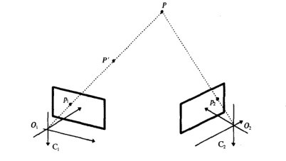
根据双目视觉原理(下图),求取空间点的三位坐标需要至少两个相机从不同视角观察到同一空间点。
而从两张图片做立体匹配不是一件容易的事。为此我们用一个激光代替其中一个相机,组成激光相机三维重建系统。其中激光可以是点激光、线激光、投影仪等。甚至如果使用投影仪的话,投影仪的数学模型可以使用相机针孔模型来表示。再此本文仅简要介绍线激光的情况。
线状结构光三维重构系统是一种不需要进行复杂立体匹配过程的三维重构技术。如下图所示,线结构光系统一般由的一个线状激光器和一个数字摄像机组成。
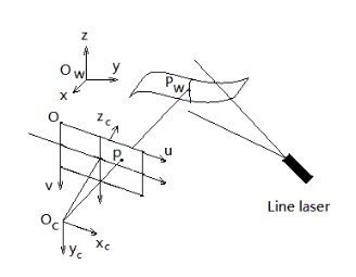
世界坐标系中一点Pw在激光平面上也,并且成像于相机像平面p上。通过这一关系,即可计算出该点的三位坐标。当相机和线激光以适当的方式固定好以后,就需要对这一系统进行标定,才能进行相关测量任务。这一标定过程包括相机标定和线激光光平面标定两部分。
在线结构光三维重构系统中,控制点(control point)扮演着一种非常重要的角色。所谓的控制点即是光平面上的点与其在相机成像平面上所形成的像点的对应。假设光平面上的某一点坐标为Pw,该点在摄像机成像平面上的像点的像素坐标为p(u,v),则这一对点称为一对控制点。为了获得线状结构光三维重构系统的标定参数,需要获取一些控制点构成的点集。Zhou等人在2005提出一种不需要知道标定板运动情况的控制点求取方法,该方法得到了比较广泛的运用,因为标定过程只需要一块标定板,且可任意放置于相机前方。
得到一系列控制点后,一般有两种方法来建立重构模型,一种是计算出线结构光光平面在相机坐标系下的表示即完成结构光的标定,另一种是建立光平面到像平面的映射关系(单应性映射)。在此仅讨论前一种情况。
将控制点坐标转化到相机坐标系下的表示,然后拟合空间平面,即完成。
本人实现的标定实例软件:
Calibration tool for 3D scanner based on line laser and camera
This tool is available for free now!
It is designed to calibrate the line structured light sensor automatically as well as the camera parameters, and the 3D scanner system usually is something like the figure shown below, where a camera and a laser are firmly fixed together.
###
Just clicking the laserScanner.exe file in this directory to open the mainwindow, there is a calibration menu in the menu bar, and activating it the calibration window will show you on the screen if no problem occurs and then you can have a try. By the way, there are some example images in the exampleImage subdirectory.
Tested on win10-64bit, win7-64bit and ubuntu1604-64bit, however this version is not for any Linux system.
If there is anything puzzling around you about this software, please send an email to me, and I will try my best.
Email:jah10527@126.com
Antonio Fan
March 30th 2017
Beijing China
update
A new test program released at April 22nd 2018, named LineLaserCalibration-2018.4.exe
A new test program released at June 3rd 2019, named LineLaserCalibration-2019.6.exe
- more robust
- add visualization
There is a reconstruct.cpp file along with the tool, which you can exploit to reconstruct anything as your like.
A new test program released at Dec. 26, 2020, named LineLaserCalibration-2020.12.exe
- add log file, which can be helpful to check whether your images are good enough when finding chessboard via cv::findChessboardCorners(gray, patternsize, corners, cv::CALIB_CB_ADAPTIVE_THRESH + cv::CALIB_CB_NORMALIZE_IMAGE);
guidance
The main window will show like below when you double click LineLaserCalibration-2020.12.exe. and welcome to donate!
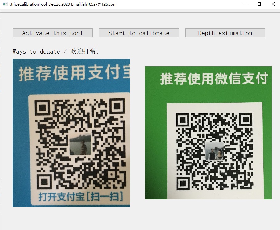
You are supposed to activate this tool at first before have a try to calibrate for every time you open this tool. Clicking the calibrate button, the calibrate window will show as below.
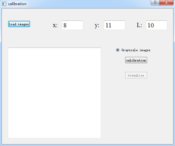
The load images button are used to select the images for calibrate. Once a directory is selected all the images in the fold are listed in the text browser below the button. Then clicking the calibration button, the camera parameter and the light plain parameter are estimated at the same time. (Some images are shown in the process, just pressing any key to continue.)
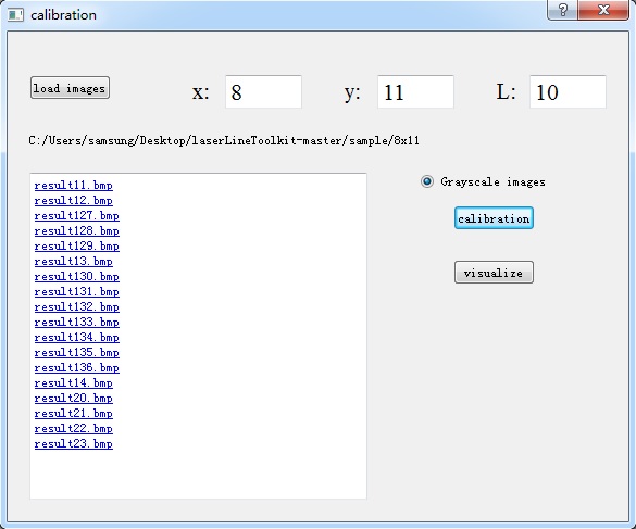
The results are written in the same directory as the exe, which are called like camera_result....txt for camera parameter and stripe_result....txt for laser parameter.
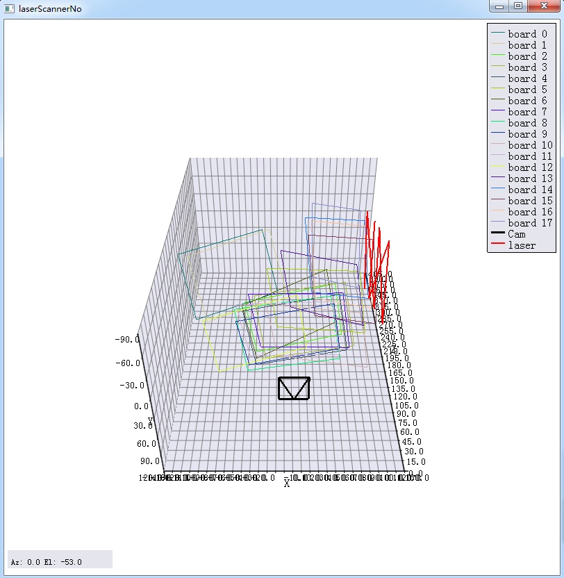
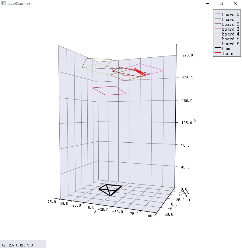
If you want to get a direct view of the result in 3D space, you can click the visualize button and the figure maybe like as below.
Tips
One should avoid the bad situation that those lines containing control points are co-linear and close to each other as below.
The cv::findChessboardCorners may be time-consuming, just be patient.
June 5th 2019.
前一篇这个主题的博文在:
Welcome to donate